RLTDR
3 in 1
Reflected Light Time Differential / Optical Time Domain Reflectometer/ microphone
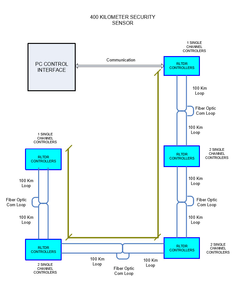
- Long range perimeter sensor up to 100 kilometers in total perimeter length (or 50km for looped zones)
- Accuracy of +/- 5 meter detection ( OTDR work when the fiber is cut)
- Utilizes a newly developed patent pending technology
- Offers a unique and easily deployed intrusion detection system
- Offers major cost reduction over other fiber solutions
- Dual fibers in a single jacket provides more accurate signal response
The system can be used at:
Borders, Airports, Prisons, Pipe Lines, Railroad Tracks, Oil Platforms, Nuclear Plants, Chemical Plants, Government Installations and other High Security Facilities.
The system alarm can also provide a GPS location to a DRONE for dispatch to the intrusion site for immediate inspection.

RLTDR FIBER SENSOR Operational Characteristics:
- Derived from BEI’s unique Fiber Sensor technology, the RLTDR system extends the perimeter protected zone length up to 100 kilometers with a dual jacketed fiber. It is easy to install and maintain.
- The RLTDR Fiber Sensor controller is housed in a 1U Rack enclosure powered by either low voltage AC or DC.
- The RLTDR Fiber Sensor interfaces via either RS232 or USB to a PC for signal processing and alarm notification.
- With the RLTDR Fiber Sensor unit there is no power required in the field for perimeters up to 100 kilometers.
RLTDR FIBER SENSOR Specifications:
- Electrical – 12 to 24 VDC or 9 to 18 VAC @ 2 amp into a 2.1mm receptacle.
- Maximum loop distance is 100 kilometers with a single controller.
- Intrusion detection zones are ±15 meters.
- 9/125μm Single mode fiber with ST fiber optic connectors
- Mechanical dimensions: 1U Rack
- Environmental: Temperature -3 to +55 degrees Centigrade
- Humidity 10-90% non-condensing
Tactical Fiber Optic Cable Specification:
- Tactical Fiber Optic Cable
- Diameter = 4.6 mm
- UV and Flame Retardant Outer Sheath
- Inner Sheath of Aramid Yarn

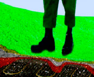
RLTDR Fiber Sensor can also be buried for invisible perimeter intrusion detections.
The head end receives the laser signals and reacts to the variations in the infrared lasers return signal. The head end controller is connected to a PC via a USB or RS232 connection to receive and process the signal to determine if an intrusion event has taken place. The software that interfaces to the controller provides a graphical representation of the perimeter and denotes the location of the incursion


